Amazon France
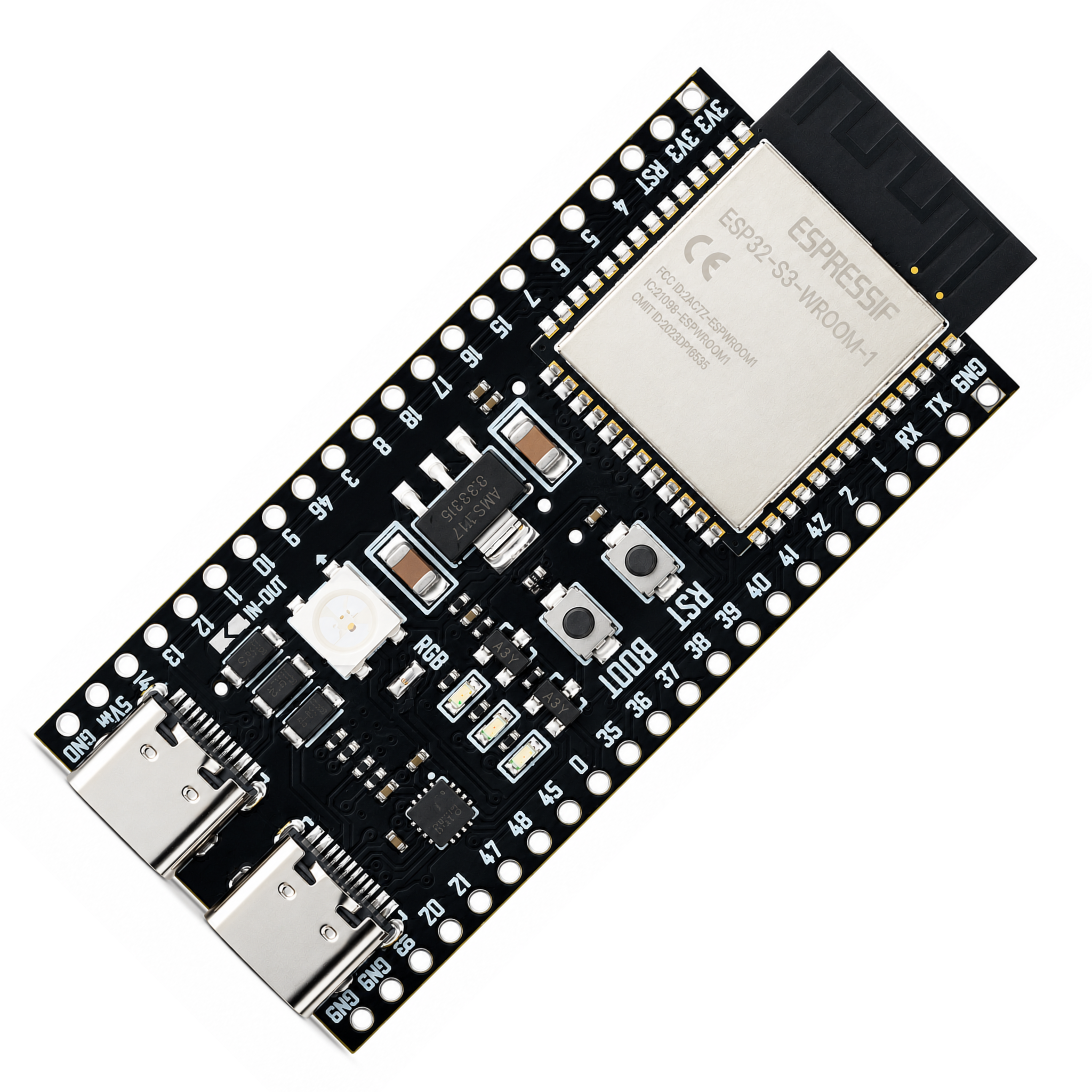
ESP32-S3 N16R8
Development board · 16 MB Flash, 8 MB octal PSRAM. GPIOs 4, 5, 6, 7, 8, 9, 15 and 16 must be accessible.
ESP32-S3 N16R8 · dual USB-C versionATELIER / DIY
Élysia invites you to build your own voice satellite for Home Assistant. Follow the component list, wiring diagram and setup steps to try it with Assist.
A DOCUMENTED BUILD
Connections are documented by pin name in the diagram below. The photos below help identify the modules. The diagram specifies electrical connections independently of their position on the board.
BEFORE YOU START
It detects “Okay Nabu” locally, sends your request to the assistant selected in Home Assistant and plays its response. Choose speech recognition, the conversation agent and the speaking voice in Home Assistant: local services or Home Assistant Cloud, depending on your setup.
You need Home Assistant with Assist configured, ESPHome Device Builder, a 2.4 GHz Wi-Fi network and a computer with USB. This single-microphone build has no acoustic echo cancellation: television and background noise can reduce detection reliability.
01 / THE COMPONENTS
The component types and specifications used in this build. Check each module’s labels and supply voltage: the same chip name does not guarantee the same pin order.
Development board · 16 MB Flash, 8 MB octal PSRAM. GPIOs 4, 5, 6, 7, 8, 9, 15 and 16 must be accessible.
ESP32-S3 N16R8 · dual USB-C version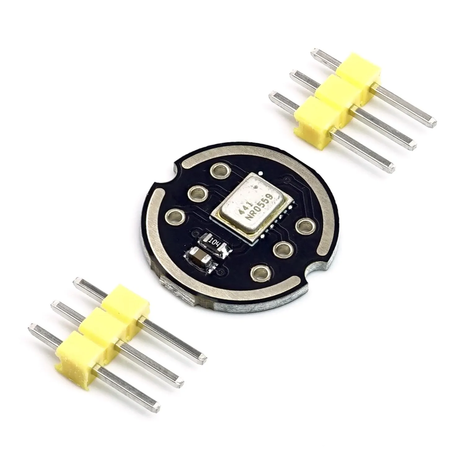
Omnidirectional I²S digital MEMS microphone · 3.3 V supply. This build uses one microphone.
INMP441 · round module with six connections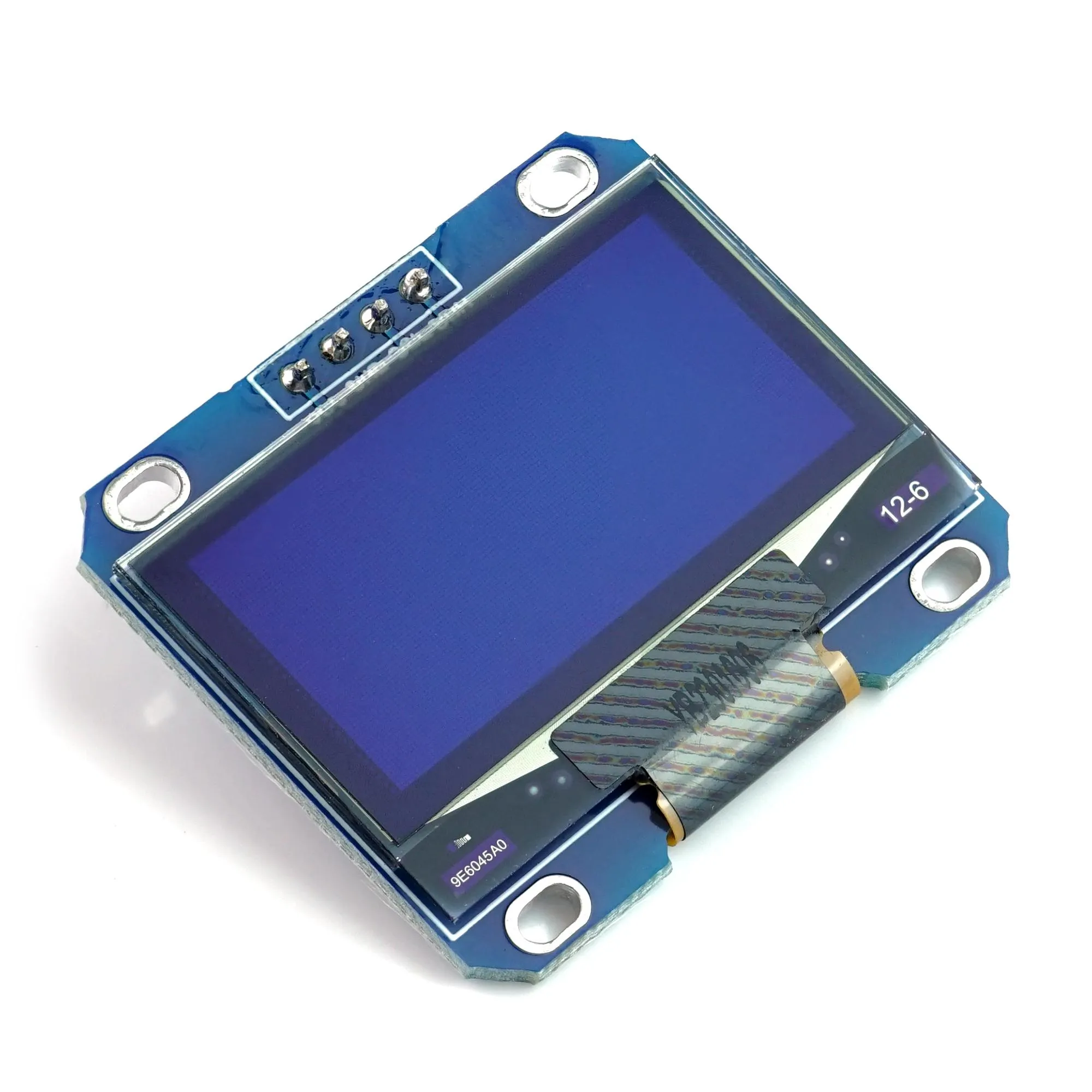
128 × 64 pixels · four-pin I²C interface. Supply must support 3.3 V. This is not an SPI display.
SH1106 · 1.3″ · four-pin I²C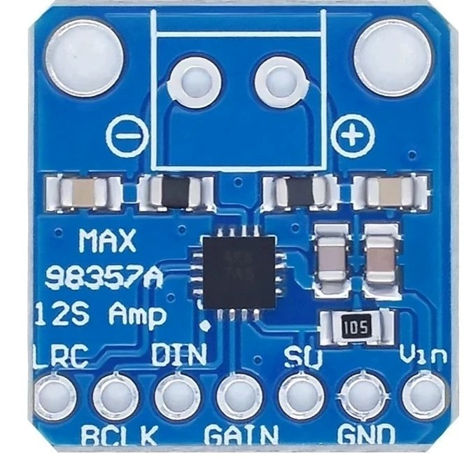
Mono class-D I²S amplifier · 5 V supply. VIN, GND, SD/EN, GAIN, DIN, BCLK and LRC connections.
MAX98357A · equivalent seven-connection module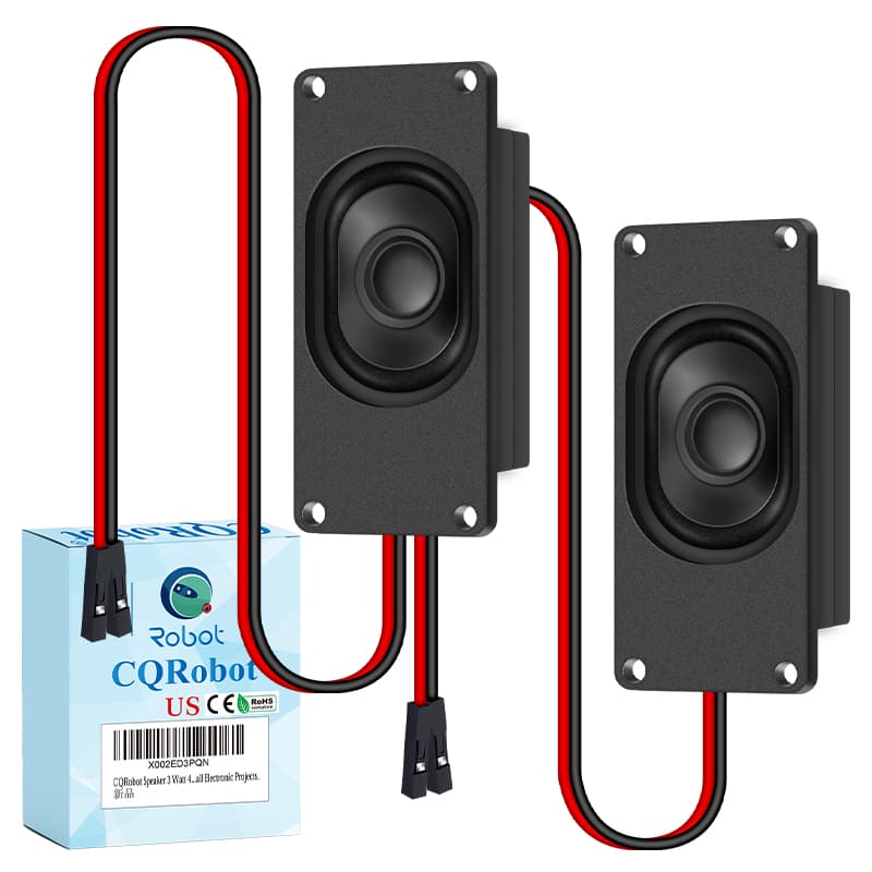
70 × 31 mm enclosed speaker, marketed as 3 W RMS. Check the exact reference: some specifications list 2 W nominal / 3 W maximum.
CQRLB4O3W-B · only one speaker is required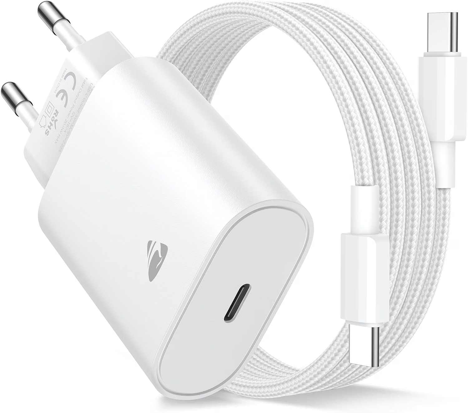
Quality regulated power supply and a USB data cable for first flashing. Use short wires and insulated connections.
Development board · 16 MB Flash, 8 MB octal PSRAM. GPIOs 4, 5, 6, 7, 8, 9, 15 and 16 must be accessible.
ESP32-S3 N16R8 · dual USB-C versionOmnidirectional I²S digital MEMS microphone · 3.3 V supply. This build uses one microphone.
INMP441 · round module with six connections128 × 64 pixels · four-pin I²C interface. Supply must support 3.3 V. This is not an SPI display.
SH1106 · 1.3″ · four-pin I²CMono class-D I²S amplifier · 5 V supply. VIN, GND, SD/EN, GAIN, DIN, BCLK and LRC connections.
MAX98357A · equivalent seven-connection module70 × 31 mm enclosed speaker, marketed as 3 W RMS. Check the exact reference: some specifications list 2 W nominal / 3 W maximum.
CQRLB4O3W-B · only one speaker is required
Quality regulated power supply and a USB data cable for first flashing. Use short wires and insulated connections.
Illustration · check the exact referenceAlso needed: short jumper wires, soldered headers or suitable soldering, an insulating support and a multimeter. Keep the microphone’s acoustic port unobstructed. Do not add a second microphone without changing the configuration.
02 / THE WIRING
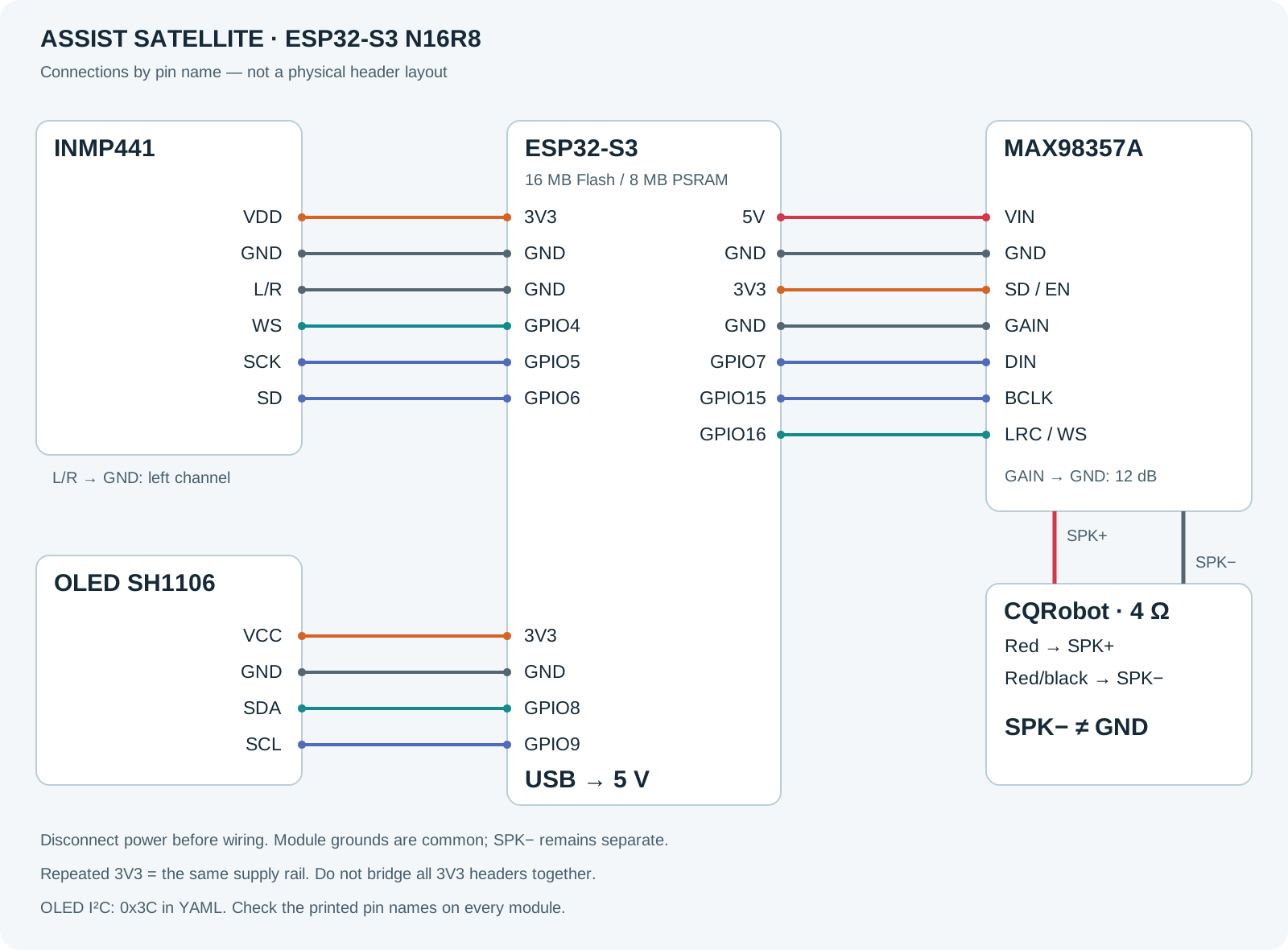
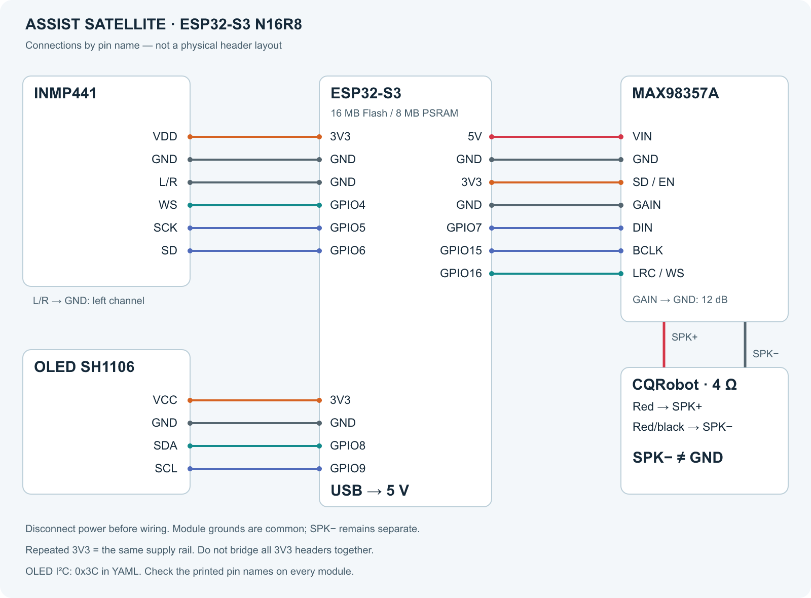
This diagram uses the reference build’s GPIOs, with GAIN connected to GND. It shows electrical connections, not the physical pin positions on every ESP32-S3 board.
| Module pin | ESP32-S3 |
|---|---|
| VDD | 3V3 |
| GND | GND |
| L/R | GND |
| WS | GPIO4 |
| SCK | GPIO5 |
| SD | GPIO6 |
| Module pin | ESP32-S3 |
|---|---|
| VIN | 5V |
| GND | GND |
| SD / EN | 3V3 |
| GAIN | GND |
| DIN | GPIO7 |
| BCLK | GPIO15 |
| LRC / WS | GPIO16 |
| Module pin | ESP32-S3 |
|---|---|
| VCC | 3V3 |
| GND | GND |
| SDA | GPIO8 |
| SCL | GPIO9 |
For the described speaker, connect the red lead to SPK+ and the red/black lead to SPK−. Neither speaker output goes to GND: the amplifier has a differential output.
Disconnect power before wiring. INMP441 and OLED use 3.3 V; amplifier VIN uses the ESP32’s 5 V pin. All module grounds connect to GND. Repeated 3V3 labels refer to the same rail: distribute it to the modules; there is no need to bridge every 3V3 header on the board.
L/R to GND selects the microphone’s left channel. SD/EN at 3.3 V enables the amplifier; GAIN to GND selects 12 dB on the MAX98357A. This does not raise its maximum power. Follow the INMP441 datasheet’s decoupling and SD pull-down requirements if they are not present on your breakout.
03 / THE SOFTWARE
In Settings → Voice assistants, create an assistant in your language. Select Home Assistant as the conversation agent, then working speech-to-text and text-to-speech providers. Home Assistant Cloud can provide both; Whisper and Piper are local alternatives, not requirements. Expose the devices you want Assist to control.
Download the source kit below. In the ESPHome Device Builder configuration directory, copy satellite-assist.yaml and the kit’s models and assets folders. Add the four values from secrets.example.yaml to your existing secrets.yaml without replacing other secrets. Generate your own keys below and enter your Wi-Fi details.
In ESPHome Device Builder, open satellite-assist, select Install → Manual download and choose Factory format for the initial flash. Connect the board with a USB data cable, preferably through UART. Open web.esphome.io in Chrome or Edge, connect to the serial port and install the generated Factory file. Safari does not provide this Web Serial installation path.
Disconnect USB, assemble the wiring and check the indicated supply connections and absence of shorts between rails. Pay particular attention to 3V3/5V and SPK−/GND. Then use one USB 5 V supply; do not add an external supply to the 5 V header while USB powers the board.
After the board joins Wi-Fi, add the discovered satellite in Settings → Devices & services → ESPHome. Enter satellite_api_key if requested. In the satellite settings, select the assistant prepared in step 1.
Configuration, Okay Nabu model, font, licenses and secrets example.
ESPHome 2026.9.0 baseline. Compile for your own setup; this public variant still needs an on-device trial.
Keys are generated in your browser and are not sent to this site. Keep them for pairing and future updates. Replace both Wi-Fi values before compiling.
04 / THE FIRST TEST
Start in a quiet room, at close range and moderate volume. Ask for simple information, then try a light exposed to Assist. Check wake-word detection, recognized text, the response and sound separately.
Press BOOT after startup to begin a request or stop the exchange. Micro coupé provides software microphone muting. Wake-word detection pauses while a reply plays; this kit does not promise voice interruption over speaker playback.
Adjust volume in the Réponse vocale media-player entity. Increase gradually and reduce it if sound distorts. The SH1106 display uses address 0x3C; if the I²C scan reports 0x3D, change address in the YAML. Later updates can use Wi-Fi from ESPHome Device Builder with your saved credentials.
Check for a TTS response in Assist debug, media-player volume, 5 V VIN, 3.3 V SD/EN and DIN/BCLK/LRC wiring. The speaker’s red/black lead goes to SPK−, not GND.
Okay Nabu detection and speech transcription are separate steps. Check the transcription engine and language in Assist, distance and background noise. A correctly transcribed but incorrectly executed request points instead to the conversation agent or exposed devices.
Try a data cable and the UART port. To enter flashing mode, hold BOOT, press and release RESET, then release BOOT. This applies to the ESP32, not the Home Assistant server.
ESPHome Voice Assistant ↗ · microWakeWord ↗ · SH1106 ↗ · MAX98357A ↗ · INMP441 ↗ · CQRobot ↗ · Home Assistant Assist ↗
Leave your email to hear when subscriptions open. No commitment.